CONSTRUCTING A SOUNDPROOFED TEST CHAMBER
Soundproofed chambers are often required for testing noisy machinery and equipment such as highly tuned engines inside a much larger building so this article will describe how it should be done. This is something that we are often asked to help with so rather than talking people through what is required, I am going to refer them to this article now being written on how to construct a test cell inside a larger building.
The principle of constructing a soundproofed test chamber remain the same and goes back to the “room within a room” method of soundproofing. First of all you have to decide if it is to be masonry or stud construction so we will deal with masonry first. A masonry constructed test chamber will obviously be stronger, will withstand a lot of rough treatment but should only be built if it is to be a permanent structure. This is because it will be harder and messier to remove when it is no longer required. So if it is to be masonry the following will describe how it is done but before we start you may want to know about vision panels (windows) and doors which we will leave to last because the principles of soundproofing with those remain the same regardless of the type of structure they are in.
Walls - Masonry
Concrete blocks are best and the higher the density they are along with maximum thickness, the more efficient they will be. The walls should be constructed first as a single skin and with no wall ties for the second skin when it is built. Build all of the walls leaving the space required for the vision panels and doors up to the height required and as shown in this illustration.
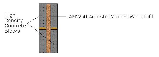
Now you can start building the second skin 50mm away from the first but infilling the void with 50mm of AMW type Acoustic Mineral Wool (AMW50). This will act as a sound absorber within the cavity enhancing the soundproofing value of the walls and will also stop mortar from bridging the two leafs. It is very important that no bridging of mortar occurs otherwise it will substantially reduce the efficiency of the soundproofed walls. The best way to avoid this is to always ensure the AMW is higher than the wall being built. Once the second leaf has been constructed we need to consider the roof. Regardless of whether the roof is going to be concrete or timber joisted there should be a set of timber joists fitted inside the inner walls near the top but not at the top and supported on wall fixed wallhangers. If the roof is to be concrete the top of the joists can be 25mm or more from the top of the walls as shown in the nextillustration.
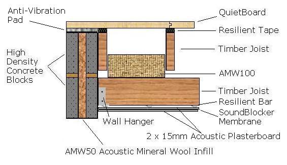
If timber joisted then the lower set of joists should be far enough down the walls to accommodate the second set that will be flush with the top of the walls. It is important that the lower set of joists do not come into contact with either the top set of joists or the concrete. The joists should be spaced at 450mm centres and of suitable dimensions to support the weight of the 30mm (2 x 15mm) high density plasterboard that will be screwed to it with our 2kg/m2 SoundBlocker Membrane sandwiched between the layers. The way to fix this is to screw up the first layer of Acoustic Plasterboard to the underside of the joists. 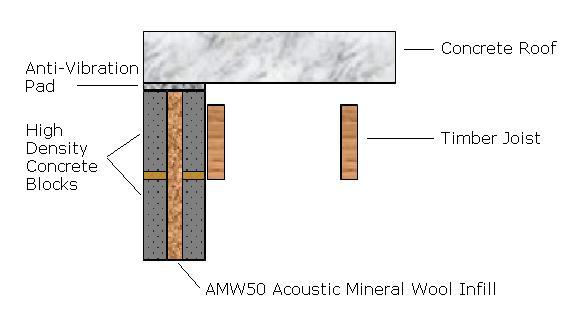
Then glue the SoundBlocker Membrane suitably cut to size to the second layer of plasterboard then screw it to the first layer as one, being sure the screws are going into the joists and not just the plasterboard.
100mm of AMW100 can now be installed between the joists from above as a loose fit. It is a mistake to jam it in tightly because sound absorbing and soundproofing efficiency is reduced. Loose is good, Once completed the roof should be similar to the next illustration.
Walls – Stud
If a more temporary test chamber is required then the walls can be constructed using stud framing. Either timber or metal stud can be used but the metal stud will give improved results. Construction is similar to the masonry walls above and built one at a time. So using 75mm stud construct the first wall to the dimensions required fitting just a sole plate, top plate and uprights at 600mm centres but with no noggins. (Noggins are the cross pieces usually fitted at 600mm spacings). (See following illustion).
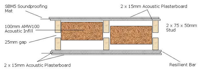
The frame should be decoupled from the floor using 75 x 10mm Acoustic Foam Tape or our Anti-Vibration Mat. Once completed, fit the ceiling joists as described earlier giving you a reasonably rigid construction. On the inside face of the stud walls, screw our 15mm Resilient Bars or the more efficient GenieClip system at 600mm centres from floor to ceiling. The same can be used across the ceiling joists but at 400mm centres.
Now 15mm of Acoustic Plasterboard can screwed to the bars followed by 2mm of SBM5 soundproofing mat followed by another layer of 15mm Acoustic Plasterboard. The ceiling above will be treated in a similar way but as described earlier.
Once completed the second stud wall can be begun and should be fitted 25mm away from the first set but this time with noggins and to the same height as the first walls. Infill with 100mm of AMW100 again as a loose fit then clad with 30mm of Acoustic Plasterboard with the soundproofing mat sandwiched between the two layers as before. Or for further improved result, use our 50mm SoundBlocker Quilt but this has to be fixed into the first frame before the outside frames are constructed. If SoundBlocker Quilt is used then there is no requirement for additional AMW.
Roofs
Roof on Masonry Walls
Concrete roofs can be cast in situ supported by profiled steel or far better is to install solid concrete beams tightly butted to one another and bridging the top of the walls but isolated with our 10mm Anti-Vibration Mat as shown in an illustration above. The mat can be cut to size from our 1m x 1m sheets. Once installed the joints of the beams should be sealed with our Acoustic Sealant.
If the roof of the test cell is to be timber the supporting joists should be level with the top of the walls as previously stated. All that remains is to still glue the 10mm AV Mat to the top of the walls with a gun applied adhesive and also apply it to the top of the joists but for the joists it may be easier to use our 10mm self-adhesive Acoustic Foam Tape. As shown in an illustration above, on top of this should be screwed our 18mm high density QuietBoard t&g acoustic panels. These should be installed screwed down to the joists (not too tightly) and with the joints glued with normal PVA type wood glue. Any gaps that might be evident anywhere in the roof should be sealed with our Acoustic Sealant once finished.
Roof of Stud Walls
For obvious reasons these can only be timber joisted and should be installed as described in the above section.
Windows
Windows or otherwise known as vision panels can now be added if required and fitted into the window frame that should line the opening using 25mm thickness planed timber and isolated from the walls with AV Mats or Acoustic Foam Tape. Using three different thicknesses of glass one of which should be laminated, they should be installed in any order the width of the wall or to the desired width (the wider the better) fixed with quadrant and sealed in with clear silicone sealer as in the following detail.
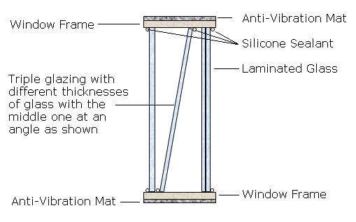
The most important thing is the middle pane should be off centre and installed at an angle. If there is a risk of the panes fogging up, install moisture absorbing crystals between the panes when they are being installed.
Doors
An acoustic test cell will require a double swing door entry system to allow access by vehicles or a single door just for pedestrians. If budget does not allow for the installation of a purpose made acoustic doorset, then solid, thick, heavy doors can be used. For a single door good results can be achieved using a heavy fire door fitted with acoustic door seals. One of these would give an insulation value of around 30dB but if a higher value is required then a double entry door system would be required when a person has to open two doors to obtain entry. Both doors should be sealed when fitted and the spacing between the doors as wide as possible. Because these doors would be sealed when closed it is more difficult to open and close them quickly, so patience is required. The door frame should be fitted in the same manner as the window frame but using thicker timber. A 25mm doorstop will be required for the door to close against which will also be required on the threshold although here it could be reduced to 20mm. Using our self-adhesive triangular ‘Batwing Seals’ they are fitted into the corner of the doorstop where it is fixed to the frame so that when the door closes, all of the edges of the door are sealed as shown.

For double doors, because each leaf of these is likely to be much larger than normal personnel doors, if you do not want the expense of bespoke acoustic doorsets they can be made as follows.
Using minimum 50mm thick, high density t&g hardwood panels that may have to be produced for you by your local timber supplier, construct the doors to the required size with all of the joints glued. Once assembled, the faces can be further sealed with 12mm plywood or MDF. These should be fitted in a similar manner to the single doors using the same seals. A double door entry for double swing doors is not usually practicable so for best results they need to be as thick as possible.
Finishing
Now you have a completed test chamber with an average insulation value that should be in excess of 50dB taking into account the windows and doors that will not be performing as well as the walls and roof. So now the construction is finished, some thought must be given to lining the inside with a suitable sound absorber to enhance the sound blocking performance of the chamber. If budget is an issue, simply fix 50mm stud to the inside faces of the test chamber making sure the screws do not penetrate the supporting stud but only fix into the Resilient Bars or GenieClip bars. Now glue 50mm of AMW50 to the walls and ceiling using Sta-Put, our aerosol contact adhesive before overcladding with 20g galvanised perforated steel.

Alternatively, our Steelsorption sound absorbing panels can be used.
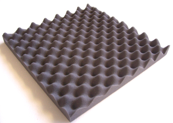
Or if durability is not an issue the walls and ceiling can simply be lined with our EggBox or Wedge style profiled sound absorbing foam that are simply glued directly with no additional screws.
Ventilation
Ventilation will be required if the test chamber is to be used for vehicles so thought will have to be given to ducting the intake of air and exhaust fumes and for this we suggest you contact the manufacturers of silencers applicable for your usage. If the test cell is only to be used for people then ventilation may still be required to stop the air from becoming stale and stuffy. Usually two passive vents would be required and for these we can offer our Acoustic Vents with an average value of around 40dB.
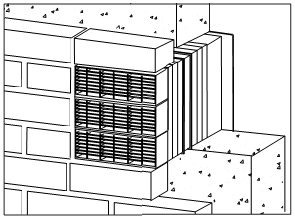
These would situated diametrically opposite each other so that on one wall the vent is high and on the opposite wall the vent is low down. If forced air is required then a slow running fan should be used and mounted on the outside of the test cell inside extended ducting using ply or MDF and lined with sound absorbing foam on the inside.
Final Note
Details of all the acoustic products mentioned in this article can be supplied by us and if you click on the name of any particular item above, it will take you through to more information for that product.
I hope you have found this article useful in helping you understand what is required to construct your own acoustic test chamber on a budget but like most other people, I am sure some things may have been missed so please our technical department if you think this information can be changed for the better in any way. Contact details for all of our departments can be found on the contact us page on this web site.
Written by Stephen Young
© Sound Service (Oxford) Ltd 2014


